Deleted
Deleted Member
Posts: 0
|
Post by Deleted on Oct 27, 2014 16:24:28 GMT -5
I'm sorry for such a late answer! Everything looks OK in the photos. Do you have anthing connected via MIDI that could generate weird MIDI-notes?
Since the input worked with other pads, you don't need to open the module.
I would suggest you try a different (new?) cable for the hihat. Cables sometimes break, and both the pad and the module seems fine.
/Krillo
|
|
|
|
Post by lucsnarewalker on Nov 4, 2014 11:29:54 GMT -5
I took my equipment to a repair lab.
They replaced the black rectangle 8 pin chip ("signal amplifier", if I understood well) of the hi hat PCB, but apparently the problem is still there.
They are going to look for a new "hall effect" chip.
Do you know if these 2 chips are likely to malfunction after a certain period of time ?
|
|
|
|
Post by lucsnarewalker on Dec 9, 2014 10:01:40 GMT -5
Here is additional information to my previous post :
1) The repair lab seems to have a hard time finding the same hall effect chip.
2) Also they tell me that the magnet of the clutch is likely to have weakened.
They removed the thin dark metal plate (of the hi hat cymbal) against which the clutch hits down, and replaced it by thin cardboard so that the magnet ends closer to the sensor.
3) Last, apparently they have tried to adjust the level of sensitivity of an element of the PCB (knob on one of the chips, if I have understood well).
I now get a better response when closing the hi hat pedal, but not as good as before.
Here are my questions :
- Is it really likely that the hall effect chip has worn out, and does it have to be replaced by the exact same chip (ref. HAL 508 if I am correct) ?
- How should the knob on the PCB be set ?
- Can the response improvement really be due to the magnet ending closer to the sensor (thanks to the thin card board placed by the repair lab) ?
- Is it really possible that the magnet has become weaker, and how can I measure this, and find a new one ?
Thanks in advance for your precious help !
|
|
Deleted
Deleted Member
Posts: 0
|
Post by Deleted on Dec 28, 2014 19:32:10 GMT -5
Here are my questions :- Is it really likely that the hall effect chip has worn out, and does it have to be replaced by the exact same chip (ref. HAL 508 if I am correct) ? Again sorry for another late answer :/ 508 is correct. I don't think the chip could be worn out. Either it works, or not... - How should the knob on the PCB be set ?I don't know. Maybe it's possible to see the position in the photos I have shared in this thread. But I remember that there is "glue" on the pot, so probably it's not possible to see the position  - Can the response improvement really be due to the magnet ending closer to the sensor (thanks to the thin card board placed by the repair lab) ?
Yes. On my hihat controller, I have put a piece of paper where the clutch "hits" because it is usually too strong. [/b][/u]- Is it really possible that the magnet has become weaker, and how can I measure this, and find a new one ?[/quote] Yes. Magnets can be de-magnetized by heat, strong vibrations and strong alternating magnetic fields. Maybe you remember those defluxers that was used to demagnetize tapedeck heads?  Try a very strong magnet and see if the hihat works "better" or differently. Also, if you or the repair lab has access to an oscilloscope you can check the DC on the ring of the stereocable to the hihat controller. This should move slowly as you move the clutch. If it moves rapidly or erraticly, this could explain the behavior of the hihat triggering. If you want to buy a new magnet I recommend www.supermagnete.deNOTE: I have not used their magnets for the dd4 hihat, so I do not guarantee their products in any way. Thanks in advance for your precious help ! I'm glad if I can help!  |
|
|
|
Post by lucsnarewalker on Jan 12, 2015 5:06:28 GMT -5
Thank you again for your reply !
On the link you placed earlier in this post there is a Micronas document containing several processors, including the HAL 508.
Based on that (and on the "AS 508" writing marked on the captor), I ordered from Micronas several pieces of the HAL 508. The repair lab tested them on my PCB, but apparently the HAL 508 is not compatible (no signal at all said the repair lab, due to improper magnetic response characteristics supposedly).
- How did you end up with this Micronas product ?
- Did you test it yourself ?
- What type of magnetic response characteristic must the captor have ?
The repair lab told me that the only inscription on the original captor (on its hidden side when soldered on the PCB) is AS 508, but it is impossible to find this very reference on the internet and in stores apparently.
Also, earlier in this post, you mention : A1301, A1302, and UGN3503.
- How did you end up with these products, and did you test them ?
- Are they all similar, and what is the technical difference with HAL 508 ?
- What type of magnetic response characteristics do they have ?
- What company manufactures these products ?
In my case, the pad now responds a little better to opening and closing actions (with the thin piece of cardboard placed instead of the black "removable"metal plate of the pad).
Does this mean that my hall effect sensor is totally ok, and the problem is elsewhere (magnet...) ?
- Is the piece of paper you are talking about placed on top of the black "removable"metal plate ot the pad, or does it replace the metal plate ?
- What did you want to say by "it is usually too strong" ?
- Do you still have the layer of foam glued to the base of your clutch (for softer contact with the metal plate of the pad) ?
- How did you end up with the idea of placing a piece of paper ?
Sincerely.
|
|
Deleted
Deleted Member
Posts: 0
|
Post by Deleted on Feb 17, 2015 5:31:23 GMT -5
- How did you end up with this Micronas product ? It's from what I could read off of the components.- Did you test it yourself ? No, unfortunately not. :/ - What type of magnetic response characteristic must the captor have ? I don't know.Also, earlier in this post, you mention : A1301, A1302, and UGN3503. - How did you end up with these products, and did you test them ? From what I found by looking at spec sheets, I found them to be compatible. I might be mistaken though.- Are they all similar, and what is the technical difference with HAL 508 ? I found them to be compatible. I might be mistaken though.- What type of magnetic response characteristics do they have ? I don't know.- What company manufactures these products ? I don't know.- Does this mean that my hall effect sensor is totally ok, and the problem is elsewhere (magnet...) ? On my hihat controller, I have put a piece of paper where the clutch "hits" because it is usually too strong. - Is the piece of paper you are talking about placed on top of the black "removable"metal plate ot the pad, or does it replace the metal plate ? It's where the clutch hits. There should be no removable part.- What did you want to say by "it is usually too strong" ? I found that "half open"-type sounds were seldom triggered, and also foot-chicks were always velocity 127 without the paper.- Do you still have the layer of foam glued to the base of your clutch (for softer contact with the metal plate of the pad) ? Yes.- How did you end up with the idea of placing a piece of paper ? It was basically thin enough.Let me just say that I documented the hihat circuitboard for anyone wanting to DIY it. I can unfortunately not guarantee I have gotten it all correct.  For you, I would recommend taking out the circuit board and hooking it up to the dd4, hooking up the dd4 midi out to a computer and run MIDI-OX and see what data you get by having a strong magnet in proximity to the circuitboard. If you get MIDI data, then the circuit should be OK. |
|
|
|
Post by lucsnarewalker on Mar 17, 2015 10:00:13 GMT -5
Thank you for your reply ! (this time I did no receive the email warning me of your reply, that's why I am now replying to you late)
In the last part of my previous post, I was asking for precisions about the piece of paper you placed where the clutch hits.
In your answers, you say that there is no removable part.
However, the area where the clutch hits is a removable black piece of metal (both square and circular shaped) screwed to the black metal block, right on top of the green PCB.
Could you please confirm me that your piece of paper is placed on top of that removable plate (I mean, "in addition to it", not "instead of it") ?
Also, what made you add something to the pad (I mean "add a piece of paper") ?
Is it only "I found that "half open"-type sounds were seldom triggered, and also foot-chicks were always velocity 127 without the paper." ?
Thanks again.
|
|
|
|
Post by ckimyt on Apr 30, 2015 18:48:51 GMT -5
FYI, I've just tried to build the circuit from scratch based on the circuit on page 1 of this thread (I only bought the ddrum4 SE head, no pad hardware). I substituted an Optek OH180U, which has very similar operating characteristics as the specs in the HAL 508 sheet. Other than that, everything wired up the same...and could not get any response out of the ddrum4SE at all. I reached out to Electronics Stack Exchange (see electronics.stackexchange.com/questions/166962/problem-with-hall-effect-sensor-circuit-to-detect-magnet-position) and everyone seems pretty confused about the nature of the circuit; i.e. it's very odd that there's no separate output, and if it's acting as a parasitic load on the supply voltage for the op-amp...that can't be a good thing! I'm trying to work it out with them. Perhaps they can help me engineer a new circuit that is powered separately. |
|
Deleted
Deleted Member
Posts: 0
|
Post by Deleted on May 2, 2015 12:08:19 GMT -5
Hi
Cool to see some of my stuff getting distribution ^_^
Regarding the hihat circuit and it's function; Note that LM358 has a minimum operating voltage of just 3V. The open load voltage of the dd4 hihat sens is with my dd4 4,68V. This gives a range from 4,68 down to 3V that the hihat clutch distance can be "translated". I saw you said 8 levels, but it's actually 254 levels! Or rather the ADC in the dd4. That is pedal midi CC and then aftertouch as you press down on the hihat pedal giving 127+127 levels.
Also there is the function of registering the foot-chick. So the circuit must see a difference between slow movements and the fast movement of playing the hihat only with your foot as for example in jazz 2 and 4.
So the basic function of the circuit is to be a variable resistance that is dependant of the position of the magnet. From what I've googled up the circuit is basically a hall effect accelerometer.
Also note that on the circuit diagram, the two 5V points are connected.
|
|
|
|
Post by angr77 on Mar 18, 2018 3:24:40 GMT -5
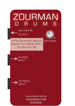
Hi! I have built a complete Roland FD-8/VH-11 hi-hat conversion module for ddrum4. It replaces the ddrum CAST hi-hat (Hall effect sensor based plus piezo) with a Roland hi-hat (resistor based plus piezo) The solution is just plug and play...only ddrum4 calibration needed and it handles the pedal plus the bow information and converts it to ddrum4 hihat signal. Full pedal articulations and foot splash is supported. Have a look at: zourman.com/product/zourman-drums-hi-hat-conversion-module-for-fd-8-vh-11-for-ddrum4-se/Best regards Anders / www.zourman.com |
|
|
|
Post by angr77 on May 10, 2020 11:26:00 GMT -5
 Hi! I was just visiting the forum - and had to write the facts that I have sold 21 units of the hi-hat conversion module for FD-8/VH-11 and ddrum4SE. :-) So the ddrum4 SE seems to be living well out there! Funfun! Big thanks and Best Regards Anders / http://www.zourman.com |
|
|
|
Post by thierry on Apr 13, 2024 16:21:42 GMT -5
   Hello all ddrummers !! Here some pictures of my own DIY hihat controler for ddrum4. It is based on a magnet at the bottom of my hihat stand moving around a hall effect sensor (in red) and the electromic based on the corrected schematic of the original ddrum4 hihat. The "pad" is made with a pair of low volume hihat cymbal heavely dampened with electric cable and a piezo sensor. I am very happy with the result.... I will be happy to post schematics and explanations if you are interested... Thierry EPPHERRE from France |
|
|
|
Post by thierry on Apr 13, 2024 16:30:19 GMT -5
And here two other pictures of my hihat .... Thierry EPPHERRE from France   |
|
|
|
Post by Valdu on Apr 13, 2024 16:46:02 GMT -5
I'd be interested by the schematics of the Hall effect sensor circuit, and the used components.
I've built a custom hi-hat pedal using a neodymium magnet, but whith an original Clavia circuit for the Hall sensor part. I'll post picture soon.
French people are present on this forum! Thierry, where are you in France?
|
|
|
|
Post by Valdu on Apr 14, 2024 6:25:05 GMT -5
|
|


